
Paulo Henrique Alfenas da Silva1, Jéssica Pereira Duarte2, Victor Bretas3 and Raphael Vieira da Costa4
1. Senior Geotechnical Consultant at Norsk Hydro, Belém, Brazil
2. Geotechnical Engineer at Pimenta de Ávila, Belo Horizonte, Brazil
3. Geotechnical Engineer at Hydro Paragominas, Brazil
4. Head of B&A Technology at Norsk Hydro, Rio de Janeiro, Brazil Corresponding author: paulo.alfenas@hydro.com
Abstract
In Brazil, the need for automatic alert system activation of tailings dams based on deformation and displacement criteria raised the importance of stress-strain modeling as a fundamental approach. Understanding the stress-strain behavior of the materials that composes a geotechnical structure is relevant for a fair estimate of its displacements, complementing the evaluation of their operational and safety aspects. However, the components materials of a geotechnical structure present natural variability in their properties inherent to their state. This study proposes a phenomenological approach to simulate the deformability behavior. Additionally, this paper presents the calibration of such parameters based on laboratory and field tests and monitoring data, aiming to reduce the uncertainties and better characterize their behavior. A numerical stress- strain model developed considered the finite element method and classical constitutive stress- strain models, such as the Linear Elastic and the Elastic Perfectly-Plastic Mohr-Coulomb model. The simulations considered the constructive sequence of a bauxite tailings dam and its history of tensions and displacements based on project aspects, loadings, and the construction timeline. Also, to characterize the constitutive models, a statistical evaluation of each material’s strength and deformability parameters was considered from laboratory and field tests – mainly SPT and CPTu. Additionally, the back-analysis based on the field monitoring data registered by the inclinometers installed in the structure for the past five years supported the refinement of the input parameters. As a result, after calibrating the deformability parameters, the numerical model could satisfactorily replicate the displacement registered by the field monitoring instruments. The model is the primary tool to define the reference displacements expected for the structure’s lifecycle.
Keywords: Stress and strain, Bauxite tailings dam, Numerical back-analysis.
1. Introduction
Tailings structures become exposed to constant changes in loads and, consequently, in their stress state. Thus, the knowledge of the stress-strain behavior becomes an important tool, identifying the influence of some physical phenomena on their safety and stability conditions, in addition to allowing a better understanding of the expected displacements for different operating conditions of the structure.
The numerical modeling results could be compared with the dam’s monitoring data and knowledge database. The main variables are absolute displacement and acceleration of change and help track anomalies or not expected behavior regarding the foundation, embankment, or instrumentation deviation.
The stress-strain behavior of the tailings dams is important not only during construction or uplifts but also because the stress-strain state of the core at the end of construction is the starting point for the subsequent analyses when subjected to different loadings and deformations during impoundment and operation [1].
The geological setting of the studied dam is located in Paragominas, representing one of the most important and expressive groupings of bauxite deposits worldwide. This province contents in the southern portion of the Itapecuru Group (K12it) from the Cretaceous, composed of archosean sandstones with crossbedding, marked by coarse to conglomeratic granulometry. In contrast, such sandstones are interspersed with pelitic levels, linked to an evolutionary moment of lower deposition energy. This group and its lithologies come from coastal, lagoon, fluvial, and tidal sedimentary environments, showing the eustatic variations that occurred over geological time [2].
In the northern portion of the bauxite deposits, the sandstones from upper-Cretaceous Ipixuna Formation (K2ip) stand out, marked by sandstones wrinkled with kaolinitic cementation and primary structures represented by crossed stratifications, with un-iron claystone levels linked to fluvial-lacustrine and estuarine environments. These layers are lithostratigraphic units belonging to the Grajaú Basin. This lithostratigraphy and chronostratigraphic context are based on the Valley System foundation rocks [2].
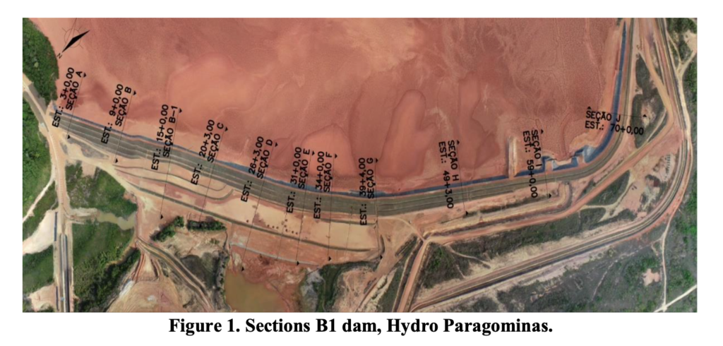
The tailings dam disposal facility, presented in Figure 1, has 1,680 m of crest length and has been five times heightened. The dam is an earth embankment, and all stages of uplift have been well documented. The instruments used in this study were inclinometer and topographic marks with regular reading since 2017.
Numerical analyses have been used to analyze the behavior of the dam body. The material parameters were obtained by conducting field sampling and laboratory tests at different dam construction and operation stages.
2. Material and Methods
Given the need to understand the deformations experienced during construction and expected for the operation of a bauxite tailings dam, a numerical model of stress, strain, and pore water pressure was developed in three steps: consolidation of the input data for the model, construction of the numerical model and calibration parameters based on monitoring data from geotechnical instrumentation installed in the field.
2.1 Consolidation of Input Data and Parameters
The structure is a compacted earth dam built on top of natural soil in a valley. A residual sandstone composes the dam’s foundation. A layer of low-resistance alluvial soil was mapped and extensively investigated. Downstream there is a sediment contention dam reservoir.
As for the tailing, after mining, using the strip-mining method, the remaining material goes through the beneficiation stage, subdivided into the following stages: crushing and storage in piles, coarse grinding and desliming, fine grinding, dewatering, and final sieving. The fine fraction resulting from these steps goes to desliming, and the overflow is thickened and pumped to the tailings reservoir. In contrast, the material coarse fraction (underflow) undergoes sequential phases of regrinding, classification, and dewatering.
Thus, the tailings reservoir was formed over the years with the continuous disposal in subsequent layers of the tailings from the bauxite beneficiation process. The system’s operation began in 2007. Currently, the operation disposes of tailings with an average solids content of 34 % and permits physical processes of drying and consolidation.
A key point in developing the numerical model was the representation of the structure characteristics and behavior. The model considered the processes of construction and raisings, the tailings disposal in layers, the seepage flow conditions, and the geotechnical behavior of the materials considering their resistance, permeability, and deformability.
In this sense, from a compilation of geotechnical tests, a statistical evaluation of the parameters of resistance, permeability, and deformability was made. Laboratory tests (oedometer and triaxial test) and field tests (Standard Penetration Test, Vane Test, and Cone Penetration Test) were considered.
The parameters of deformability were determined indirectly from the methodologies proposed in the literature [3] [4], considering correlations proposed by the authors from the results of CPT and SPT tests, respectively.
The indirect determination of Young’s modulus (E) for CPTu tests was performed as shown in Equation (1).

Where M is calculated from Equation (2).

where:
αM Coefficient determined from the normalized cone resistance (Qt) or the soil behavior type index (Ic), kPa
qt Corrected cone resistance, kPa
σv Vertical mean stress, kPa
The indirect determination of Young’s modulus (E) for the SPT tests took place as shown in Equation (3).

In addition, the model considered a timeline of construction and raising stages, the evolution of the tailings disposal, and the variation of the phreatic level of the system.
2.2 Development of the Numerical Model
The stress-strain numerical model used the finite element method. The methodology of coupled analysis of stresses, strains, and pore water pressures was applied, establishing a chain of analysis so that the subsequent analysis considered the result of cumulative stresses and pore water pressures from the previous stages.
As for the geotechnical characterization of materials, it is noteworthy that the waste material properties have a natural variability. The uncertainties of mean value and standard deviations are due to compaction conditions, formation process, and stress-state distribution, among others [5].
The constitutive models applied to materials were determined based on the statistical evaluation of geotechnical parameters and the variability observed in the investigation data. Thus, the model considered classical constitutive stress-strain models, such as the Linear Elastic model and the Elastic-Perfectly Plastic Mohr-Coulomb model.
Then, the development of the numerical model considered the constructive sequence of a tailings dam and its history of tensions and displacements, with the discretization of the geometry in layers, limited to a fixed layer height to guarantee uniform distribution of stresses throughout the model.
Briefly, a sequence of coupled analyzes of tension and pore water pressure was developed in stages, gradually simulating the construction of the dike and its raisings, in addition to the disposal in layers of the bauxite tailing at the reservoir, considering periods of consolidation, until the condition.
2.3 Model Calibration
In the absence of laboratory tests for direct determination of deformability modules, empirical correlations of the results of the SPT and CPT tests were used to estimate Young’s modulus ranges for different materials. Nevertheless, given the uncertainties and the inherent variability of the geotechnical properties of the materials, the study proposed calibration of the deformability parameters adopted.
Due to significant dispersion observed in field tests, numerical stress-strain models were calibrated by varying the mean values of deformability parameters, limited to the coefficient of variation of each material, to adjust the modelling results to installed instrumentation readings.
Thus, the historical geotechnical monitoring instrumentation installed in the structure was used as a reference, specifically the pore water pressure and depth displacement monitoring. The numerical back-analysis considered fine parameters adjustments so that the numerical results obtained were as close as possible to the monitoring data recorded by the inclinometers, from its installation to a reference reading, representative of the current condition.
3. Results and Discussion
The study’s main goal was to develop a numerical model representative enough to allow, within its limitations, to understand the general tendencies of displacement that govern the system’s behavior throughout its operation.
Within the geotechnical characterization tests of the bauxite tailings, the oedometer tests, performed in samples collected inside the reservoir, indicated that the material presents a permeability ranging between 1×10⁻⁵ cm/s and 2×10⁻⁸ cm/s.
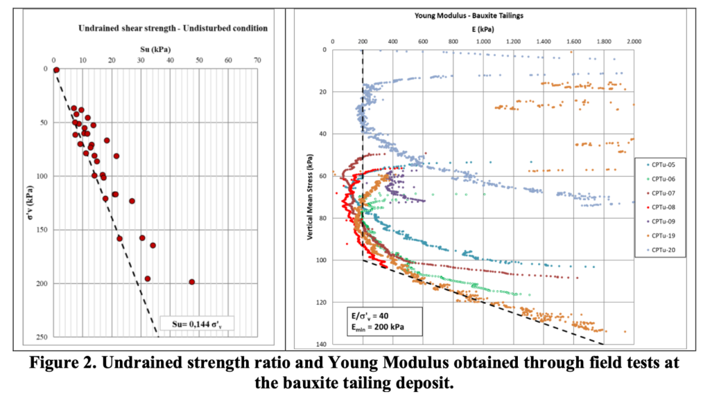
Due to the disposal method and tailings moisture, it presents a low strength with typical undrained behavior, as observed at the Vane Test performed inside the reservoir. Observing the minimum values obtained from the results of the tests in the undisturbed condition (Figure 2, left graph), undrained shear strength values (Su) varied from 7 kPa to 45 kPa, and the undrained shear ratio of Su/σ’v = 0.144.
Regarding the deformability parameters, from the correlations applied to the results of CPT tests, considerably low values of Young modulus (E) were observed for the tailings, in the order of 200 kPa, presenting a gradual increase to higher stress levels (Figure 2, right graph). The Linear Elastic constitutive model applied for the material aimed to reduce the numerical convergence errors associated with the Finite Element Method.
Similarly, the other materials present in the structure – compacted soil, the foundation of residual sandstone soil, and alluvial soil – were characterized.
The numerical model applied a sequence of coupled analyses to simulate the history of displacements and the variation of total and effective stresses and pore water pressures in the dam’s body and the foundation. So, it was possible to incorporate phenomena inherent to the operation, such as the application of loading by the structure’s weight – consecutive raisings of the dam’s body – due to the disposal of tailings inside the reservoirs, the tailings consolidation, pore water pressure dissipation, water table variation in the system, among others. Figure 3 briefly indicates the construction sequencing of the analyses.
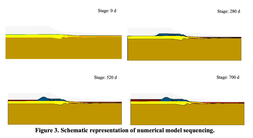
Therefore, the numerical model established a gradual sequence of construction of the dam with compacted soil and the disposal of bauxite tailings until the current condition of the operation. The application of loads was made from the subdivision of the geometry into several layers with fixed height, avoiding sudden disturbances within the stress state of the model. During the model construction, activating elements with a height greater than 2.0 m implied inaccurate results.
The structure in question features an integrated geotechnical monitoring system comprising piezometers, water level indicators, inclinometers, and instruments for monitoring surface displacements, which were fundamental to model calibration.
Since the numerical model simulates the structure’s operation throughout the construction and operation stages, the monitoring database must be robust enough to bring more assertiveness to the back-analysis and, consequently, to the calibration. The dam instrumentation had an extensive monitoring database, with readings recorded from 2017 onwards.
It is worth mentioning that, although the evaluation considers monitoring data from 2017 onwards, it was necessary to represent the prior construction stages since the model considers cumulative displacements and pore water pressures amongst the sequential analyses.
Figure 4 presents the results referring to the higher dam section. The inclinometers INC-01 and INC-02 are instruments installed on the dam’s crest, while the instrument INC-03 is installed at the berm.
The crest instruments (INC-01 and INC-02) tended to move downstream of the structure from its installation until the reference data for calibration. Evaluating the accumulated displacements of the model and the strain vectors of the finite element mesh, the downstream displacement tendency converges with the gradual rise in the tailings level and is affirmed by in situ readings.
The calibration of inclinometer INC-03 was particular since the instrument is installed in a berm close to the downstream reservoir and reaches different stratigraphy, including the dumped embankment constructed under saturated conditions. To represent this phenomenon numerically, it was necessary to consider more deformable layers in this region.
Evaluating the deformation vectors of the finite element mesh and the stratigraphic profile of the instrument, the influence of the sharp deformability in the more compressible foundation materials is noticeable, especially in the alluvial soil, approximately between the depths of 8.0 m and 15.5 m (Figure 4, INC-03), and on the berm approximately between the depths of 3.0 m and 7.0 m (Figure 4, INC-03).
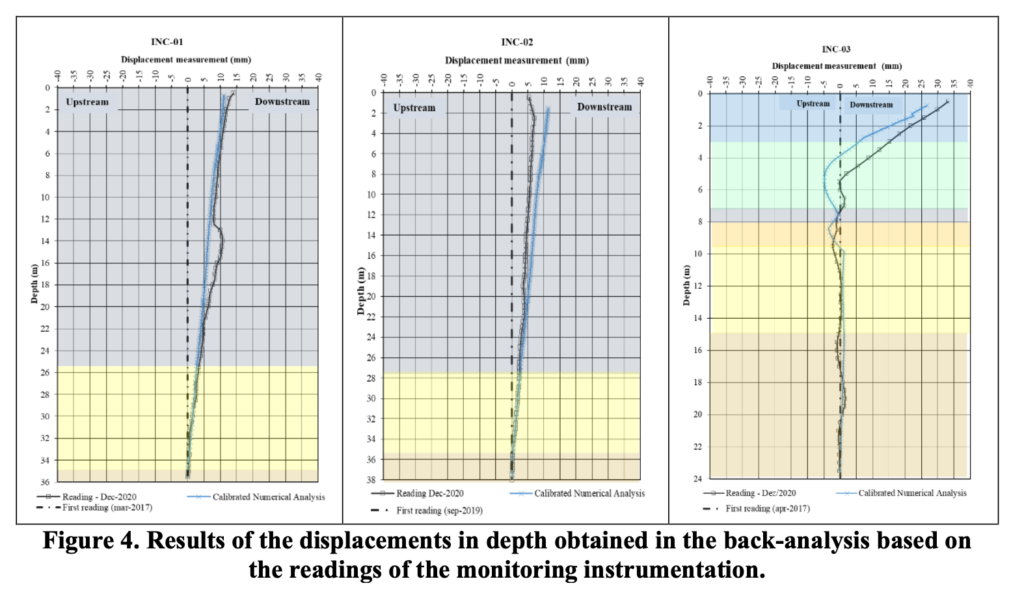
Considering the observations above and the results obtained through the back-analysis, the numerical model presented satisfactory results, presenting deviations limited to 6 mm when compared to the historical records of readings of inclinometers installed in the field, indicating the feasibility of this methodology on the definition of predictive displacements, and its use in studies for threshold references for inclinometers.
4. Conclusions
The study proposed an empirical and phenomenological methodology to evaluate the displacements experienced by a bauxite tailings dam face to a lack of laboratory-tested data. The model was constructed based on correlations with site investigations to estimate the stress-strain constitutive model. The numerical model performed stress, strain, and pore water pressure coupled analyses using the finite element method and classical constitutive models.
The model calibration considered the geotechnical monitoring database and presented satisfactory results compared to the instrumentation records. Establishing a representative range for deformability parameters limited to the coefficient of variation showed great potential to obtain better adherent results. Considering the simplified model, such as Linear Elastic, reduced the numerical errors of convergence associated with the Finite Element Method for high deformable materials inside the reservoir. Better results were observed from the subdivision of the geometry into several layers with fixed heights. Moreover, there was a need to represent all stages of construction and operation of the reservoir to consider the cumulative displacements and pore water pressure distribution amongst the sequential analyses. Finally, the monitoring database must be robust enough to bring more assertiveness to the back-analysis and, consequently, the calibration.
It is worthy to note that the present study is limited to the input and database of the instruments adopted in calibrating the numerical model. Nevertheless, the model can be understood as a primary tool to define the reference displacements expected for the structure’s lifecycle, specifically when involving non-tested materials. The authors suggest this methodology be assessed with site instrumentation readings for full laboratory-tested materials, leading to more accurate constitutive models.
5. References
- S. Feng, W. Weibiao, Kai hu, and Kaare Höeg. Stress-strain-strength behavior of asphalt core in embankment dams during construction, Construction & Building Materials 259 (2020), 119706.
- B. Kotschoubey, W. Truckenbrodt and J. M. C. Calaf, Evolução geológica da porção meridional da Província Bauxitífera de Paragominas durante o Neógeno/Pleistoceno (noroeste da Bacia Do Grajaú, nordeste do Pará e extremo oeste do Maranhão), Revista Brasileira de Geociências, 35(2), (2005), 263-272.
- P. K. Robertson, K. L. CabaL, Guide to cone penetration testing for geotechnical engineering, 2014.
- F. Schnaid, E. Odebrecht, Ensaios de campo e suas aplicações à engenharia de fundações, Second Edition, 2012.
- Dept. of safety science, Faculty of science, University of New South Wales (UNSW), Sydney, Risk Management Course notes, 2003.