
Hugo A. Brandão
Pimenta de Ávila, Nova Lima, Minas Gerais, Brazil
Rodrigo R. V. de Oliveira
Pimenta de Ávila, Nova Lima, Minas Gerais, Brazil
Luiza F. Almeida
Pimenta de Ávila, Nova Lima, Minas Gerais, Brazil
Guilherme H. S. Pinto
Pimenta de Ávila, Nova Lima, Minas Gerais, Brazil
ABSTRACT: Stability analysis is a key element of dam safety evaluation. Many safety regulations established by institutions such as Australian Committee on Large Dams (ANCOLD) or Canadian Dam Association (CDA), state that a minimum factor of safety must be achieved based on specific conditions of the dam. Current practice employs different methods of analysis such as the Limit Equilibrium Method (LEM) and the Shear Strength Reduction method (SSR) in order to estimate the dam factor of safety. The objective of this article is to analyze the advantages and disadvantages of using LEM and SSR as methods to determine the factor of safety of a dam cross section. To do so, we simulated a tailings dam with a layer of a low strength soil (colluvium) in the foundation and estimated the factor of safety using both LEM, considering circular and non-circular surfaces, and SSR methods.
1.INTRODUCTION
One of the major issues in geotechnical engineering is the study of stability in slopes and various commercial software have been developed to evaluate the stability of dam structures. The most commonly used methods to determine the Factor of Safety (FS) are the Limit Equilibrium Method (LEM) and the Shear Strength Reduction Method (SSR).
In order to evaluate dam stability, it is essential to determine a value for what will be known as the minimum factor of safety. This parameter can be defined as the relationship between resistant shear stress divided by the acting shear stress (Duncan and Wright, 2005). This parameter must be defined based on the uncertainties of the structure in hand, such as soil parameters, pore pressure conditions and others. The federal regulations and recommendations for slope stability analysis establish a minimum value of factor of safety based on each stage of dam development (e.g. end of construction, operation and closure).
Many researchers have compared the results between LEM and SSR and found similar factors of safety for similar failure surfaces. Many of these studies were limited to homogeneous soil slopes, where the geometry is relatively regular with no special features (for example the presence of a thin layer of soft material or a special geometry). In addition, comparing the critical failure surface from LEM and SSR is usually depicted as a secondary study objective, and is not highlighted in most studies. In this paper, the two methods are compared taking into considerations the same initial conditions: pore pressure, geometry and soil parameters.
Another aspect that influences the FS value is the soil’s resistance parameters. This becomes more relevant when the soil behavior, whether it is drained or undrained, determines the parameters that will be used on the analysis and in order to establish the target FS value. It is important to understand that the behavior of the material is one of the most important aspects in the selection of the appropriate method to be used, whether it is an effective stress analysis (ESA) or undrained stress analysis (USA). Indiscriminate use of ESA may completely overlook the physical behavior of the materials under shear stress, causing the stability analysis to produce a FS that misrepresents the dam’s safety conditions. Ladd (1991) defined ESA as one that assumes that the effective stress during shear is unchanged from the one immediately prior. This assumes that the shear is slow enough to dissipate the excess pore pressure and/or the excess pore pressure is low enough for the material to present an undrained behavior. This concept applies independent of the soil grain size and portrays the shear rate.
The USA is one way to consider the shear-induced pore water pressure generated by undrained shears and assumes that shearing occurs in undrained conditions. This type of analysis associates negative excess pore pressure for dilatant materials or positive excess pore pressure for contractive materials during the shear response. Thus, using the wrong analysis, ESA for contractive materials or USA for dilative materials, can lead to FS misrepresenting the structural conditions, giving a false impression of dam safety.
The Brazilian Association of Technical Standards (“Associação Brasileira de Normas Técnicas”) recommends, in the guideline ABNT NBR 13.028/2017 for dam designs, that the minimum value for the FS in an operating dam is 1.50. This recommendation also states that the designer of the dam is responsible for defining whether the analysis considers drained or undrained parameters. After the Brumadinho upstream dam collapse in January 2019, the Brazilian National Mining Agency “Agência Nacional de Mineração”), released, on August 8th of 2019, a new resolution (nº 13), setting the minimum FS as 1.30 for undrained strength parameters dam analysis.
2.METHODOLOGY
The LEM is a traditional and well-established method to determine the FS. In most cases, this solution is statically indeterminate, and some assumptions must be made to further define the FS. Morgenstern (1992), and other authors pointed that, for simple models, the FS can be numerically close when applied different methods (Janbu, Bishop, Spencer, etc). The LEM does not consider the initial stress state.
To define the FS, the LEM considers equations of balance of forces and motion along a surface to calculate the ratio between resistance and acting stress. In this method, the FS is constant along the surface, and the critical surface is the one that presents the lowest ratio between those efforts. To apply the LEM, calculation premises and methods have been developed to transform the system into an isostatic one. Each method presents specific premises that allow for the analysis of the system, satisfying one or more equilibrium equations (Duncan and Wright, 2005). A LEM analysis has the following premises (Abramson et al. 2005):
- The failure surface is well defined (circular or non-circular);
- The FS is unique and constant over the potential failure surface; and
- The Mohr-Coulomb criteria are satisfied over the potential failure surface.
To define the FS a dam stability analysis considering the LEM was developed with Slide2 (from Rocscience) and Slope/W from the GeoStudio 2020 (from Geoslope). The LEM method was applied associated with the Morgenstern – Price / GLE associated with the function f(x) = sin(x) to determinate the forces between slices. Krahn (2001) and Abramson et al. (2005) have pointed out that the function (f(x)) may be critical for some special cases, but this is generally not the case unless the problem is highly complicated.
The analysis considered three types of surfaces: (a) circular; (b) non-circular; (c) non-circular optimized. The optimization process was made with the process of surface altering, using 0,0001 to FS tolerance, in both software, which is sufficiently accurate for the present study. In both software the standard search method was applied to define the failure surface.
Optimization in slope stability analysis is used to minimizing the FS of the minimum failure surface by a nonlinear, nonconvex and discontinuous problem (Mafi et. Al 2020). Before the optimization process begins, is necessary determinate the initial shape of the potential failure surface. Then, the surface altering optimization process starts by dividing the critical slip surface into a number of straight-line segments. Next, the end points of each line segments are individually modified to evaluate the potential for a lower FS. Adjustments are then made to the next point along the slip surface until, again, the lowest factor of safety is found. This process is repeated for all the points along the slip surface until the global minimum FS is obtained (GEO-SLOPE 2015).
Another way to determine the FS is to use the SSR method. This mechanism assumes that the critical surface is associated with a shear strain zone. To evaluate the FS, this method reduces the soil parameters, cohesion and friction angle, using a reduction factor, until the failure happens due to the increase of shear stress (Matsui & San, 1992). As pointed by Cheng (2007), some advantages of this method include:
- The critical failure surface is found automatically from the shear strain arising from the application of gravity loads and the reduction of shear strength;
- It requires no assumption on the interslice shear force distribution; and
- It is applicable to many complex conditions and can give information such as stressors, movements, and pore pressures which are not possible with the LEM.
The SSR solution was applied using FLAC-Slope8.1 developed from Itasca.
3.GEOMETRY AND STRENGHT PARAMETERS
This paper presents the analysis of a theoretical dam with a height of 51m, as seen in Figure 1. The dam started with a 22m landfill (clay compacted) and was raised using compacted cyclone underflow tailings. This scenario represents a typical centerline designed dam. The dam was constructed above a 7m thick colluvium layer which is placed on residual soil. The model adopted a phreatic surface as shown in Figure 1. The materials and their properties are summarized and described in Table 1 and applied as depicted in Figure 1.
Figure 1. Model (dimensions in meters).
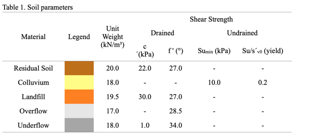
Table 1. Soil parameters
Table 1 Soil Parameters
As explained in the introduction, it is relevant to understand that the soil behavior is one of the most important issues in determining the most representative FS of the structure. In this way, the colluvium (a low resistance soil) and overflow were considered contractive under shearing and were simulated with total resistance parameters. The landfill and the underflow were compacted with quality control in order to induce a dilatant behavior during shearing and drained parameters were used for both materials. The residual soil has a dilatant behavior during shearing, so drained parameters were used for this material.
4.RESULTS
The FS calculated are shown in Table 2. There are significant differences between the FS values calculated by different methods and for different types of surfaces. The circular calculated values considering LEM method were equal to 1.50. The non-circular FS, in both LEM software, were higher than 1.30. The FS calculated with SSR and non-circular optimized LEM solutions, were lower than 1.30. The optimization process reduces the FS in 19.33% in both software. As shown in Figures 2-4 the failure surface obtained from SSR method is geometrically similar to the non-circular optimized in both software and the circular surfaces are geometrically different from all the other surfaces. This behavior is expected due to the presence of ai thin layer of low resistance soil in the foundation where the use of a non-circular surface is more suitable to represent the failure surface. The SSR solution provides a shear strain zone where the maximum increment is associated with the failure surface, as shown in this study.
 Figure 2. Comparison between circular probably failure surface and SSR max shear strain rate.
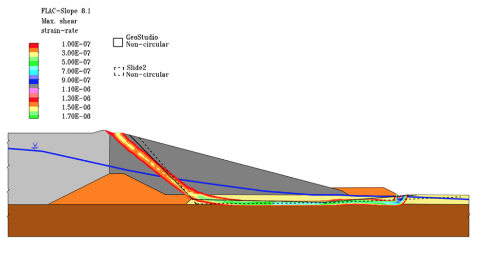 Figure 3. Comparison between non-circular probably failure surface and SSR max shear strain rate.
 Figure 4. Comparison between non-circular optimized probably failure surface and SSR max shear strain rate.
During analysis of the SSR solution, shown in Figures 2-4, the shear strain can be seen increasing from the dam crest until it reaches the toe of the dam downstream from the crest. This behavior is expected in this scenario, once the low resistance in the foundation creates a preferential failure path. This analysis can be expanded to the non-circular optimized surfaces which are geometrically similar, even though they present with lower FS values. The circular surfaces, as mentioned by Duncan and Wright (2005), are recommended for homogeneous and isotropic structures. In the analyzed dam, the low resistance colluvium layer makes the application of this type of surface not indicated.
Based on current Brazilian regulations and recommendations, this structure would meet the minimum FS stablished on resolution n°13 by ANM and ABNT NBR 13.028 if considered the circular surface (FS ≥ 1.50). If the non-circular surface were considered, the analyzed structure would meet the minimum FS of resolution n° 13 by ANM (FS ≥ 1.30), but it would not meet the minimum FS defined by ABNT NBR 13.028 (FS ≥ 1.50). The structure would not meet the minimum FS set by both Brazilian regulations when analyzed by the SSR and LEM associated with optimized non-circular surfaces. The difference between the calculated values in FS may be as high as 20%.
5.CONCLUSION
As shown by the results, if the designer considered only the LEM method associated with circular surfaces to calculate the FS, the structure would meet the minimum FS according to ABNT recommendations and the ANM regulations (FS ≥ 1.50). When considering the LEM method associated with the non-circular surface, the dam would meet the minimum FS according to the ANM resolution n° 13 (FS ≥ 1,30). If the same dam was analyzed considering the LEM method associated with optimized non-circular surfaces or the SSR method, the dam would not meet the minimum FS according to ABNT recommendation and ANM regulation (FS < 1.30).
When analyzing the geometry of the failure surfaces between both methods, the failure surface obtained using the LEM, associated with an optimized non-circular surface, has a geometry similar to the failure surface obtained with the SSR method. For the problem in question, these failure surfaces were able to adequately estimate the failure surface, resulting in a more realistic value for FS.
A comparison between the failure surfaces shows the importance of a proper selection of the selected failure surface type when calculating the dam FS. The colluvium layer under the dam creates a preferential path of the failure surface, changing the boundary conditions and, consequently, the necessary method to establish the FS value. For the evaluated scenario it would be recommended to use the SSR method or the LEM associated with the optimized non-circular surface to better estimate the FS.
It is extremely important to evaluate all possible failure surfaces when evaluating dam safety. As shown, the SSR method is an important tool to ensure the minimum FS, calculating the failure surface without any assumption of type of potential failure surface.
It is worth mentioning that, in Brazil, ABNT NBR 13.028/2017 recommendations and ANM resolution nº 13 both state that the designer is responsible for defining the minimum factor of safety for the structure. The authors strongly believe that the minimum or target factor of safety must be defined based on the variable aspects in each dam’s formation.
6.acknowledgment
The authors would like to thank Pimenta de Ávila for creating an environment that encourages technical development and a special thanks to Joaquim Pimenta de Ávila for his support in the development of this article.
REFERENCES
Abramson, L. W.; Sharma, S.; Boyce, G. M. (2º ed.) 2005 Slope Stability and Stabilization Methods. Hoboken: Wiley.
Agência Nacional de Mineração – Resolução nº 13, August 2019. Accessed in 07/11/2020. Available in: http://antigo.anm.gov.br/portal/assuntos/barragens/resolucao-anm-no-13-de-8-de-agosto-de-2019.pdf/view.
Associação Brasileira de Normas Técnicas – ABNT NBR 13028. Mining ― Preparation and presentation of design of tailings, sediments and/or water dams ― Requirements. November 2011, 3º ed, Rio de Janeiro – BR.
Cheng, Y. M., Lansivaara, T., & Wei, W. B. (2007). Two-dimensional slope stability analysis by limit equilibrium and strength reduction methods. Computers and Geotechnics, 34(3), 137–150.
Duncan, J. M.; Wright, S. G. (2º ed) 2005 Soil Strength and Slope Stability, Hoboken: Wiley.
GEO-SLOPE. 2015. Stability Modeling with SLOPE/W An Engineering Methodology. Calgary: Canada.
Herza J.; Ashley M.; Thorp J. 2017. Factor of Safety? – Do We Use It correctly? ANCOLD Conference.
Krahn J. The 2001 R.M. Hardy Lecture; the limits of limit equilibrium analysis. Canadian Geotechnical Journal 2003;40(3):643–60.
Ladd, C.C. 1991. Stability evaluation during staged construction. The 22nd Karl Terzaghi Lecture, Boston, 1986, Journal of Geotechnics Eng., ASCE, Vol. 117: pp. 537-615.
Mafra, José M. Q. 2016. Barragem construída com rejeito ciclonado: uma possível solução para disposição de rejeitos no Brasil? XVIII Congresso Brasileiro de Mecânica dos Solos e Engenharia Geotécnica., COMBRAMSEG. pp. 19-22.
Matsui, T.; San, K.C. 1992. Finite element slope stability analysis by shear strength reduction technique. Soils and Foundations, Japanese Society of Soil Mechanics and Foundation Engineering. Vol. 32, (1): pp. 59-70.
Morgenstern, N.R. 1992 The evaluation of slope stability – a 25 year perspective. Stability and performance of slopes and embankments – II, Geotechnical Special Publication No. 31, ASCE; 1992.
Ramin Mafi, Sina Javankhoshdel, Brigid Cami, Reza Jamshidi Chenari & Amir H. Gandomi (2020): Surface altering optimisation in slope stability analysis with non-circular failure for random limit equilibrium method, Georisk: Assessment and Management of Risk for Engineered Systems and Geohazards.